Limerick(9) - Cocotb Tutorial: Test Bench Structure
4/21/2023
Hello, everyone. Welcome to the nineth episode of FPGA limerick. In this episode, we will take a deep look into the test bench structure of cocotb.
As we know, cocotb stands for Coroutine Cosimulation Testbench. So before we start, we might ask ourselves: What is coroutine?
In multi-task scenario, coroutine can be viewed as a collaborative non-preemptive thread. The following shows two coroutines calling each other, with yield at every step. And the execution order will always be 1, 2, 3, 4, 5
In cocotb, the coroutine is marked by putting “async” in front of the function name. And the yield is done with “await” command. We will soon see the details when it comes to the test bench next.
The Classic Way
If you read the official document of cocotb, it uses Makefile to organize the test bench. And for each coroutine, it will be decorated @cocotb.test(), like the following example:
@cocotb.test()
async def test_xxx(dut):
…
However, what we will recommend is something different by
taking advantage of the cocotb-test framework.
Using cocotb-test Framework
The cocotb-test is a framework based on pytest. Pytest is a Python test framework that supports features like parameterized testing, assertion, which makes unit test and regression test much easier.
Also, as the test gets more and more complicated, the test bench will import more third party packages with various versions, and the environment setup gets complicated as well. To deal with that and make the test portable across different platform, we will use tox to setup the virtual environment.
So to put them together, here is what we will use as our test architecture:
With the above architecture, we will need:
1. a file called tox.ini to setup the virtual environment
2. Python files with the file names staring as “test”. This is a requirement from pytest to look for unit tests. And we will put our test bench in those python files.
This file is largely boilerplate code, with the following part that can be customized:
1. The required packages and version, such as cocotb 1.7.2
2. The environment variable. For questa sim, the LM_LICENSE_FILE needs to be setup properly.
After you type in tox in the WSL command line, the first thing it will do is to download those required packages into a local folder called .tox.
Once the packages are all in place, the pytest will look for the test_xxx.py files under its sub directories. And as a convention, we will put all of our python test code in the tb folder. Now let’s take a look at the tb/test_nco.py
1. Test Parameters
For each DUT, it usually has some parameters (or Generics in VHDL’s lingo). And the test_param will list all the possible parameter combinations that we would like to test. For example, in the Hello World example, we would like to test 3 sets of parameters:
G_CLK_RATE = 100MHz, G_OUTPUT_RATE = 24MHz
G_CLK_RATE = 100MHz, G_OUTPUT_RATE = 10MHz
G_CLK_RATE = 50MHz, G_OUTPUT_RATE = 99KHz
2. Test Prepare
Please note in this step, we will provide a function name starting with “test”. And it will also be decorated by the @pytest.mark.paramtrize to sweep all the possible parameters set in step 1.
Please also note that this function is not marked by “async”. So it is just not a coroutine. What it does is the following:
a) Optional: If SpinalHDL is used, SBT will be invoked to regenerate the Verilog/VHDL based on the test parameter
b) Compile the Verilog/VHDL source code
c) Start the simulator
In this step, Pytest will spawn a new process to communicate with the simulator.
3. Test Bench / Test Factory
There are mainly two sub-steps in step:
a) Prepare a class for the test bench, such as the class TB() in the Hello World example. This class is basically an implementation of the functional simulation approach we mentioned in previous episodes:
Please note that all the key pieces in the above diagram are implemented as coroutine in class TB() (with async mark in front of the function name)
b) Test Factory
The Test Factory will feed the Parameters into the current test run instance. Please note that the parameters from Step 2 can to be passed to this step currently, as they are run in separate processes. The way we deal with this is to save the parameters in step 2 into a local file, and read it out in this step.
And the test factory will work with a coroutine that launches the test bench, as shown in the run_test_nco function.
Posted by
FPGA Limerick
at
April 21, 2023
|
0 Comments
Limerick(8) - Cocotb Tutorial: Introduction
4/07/2023
Hello everyone, welcome to the eighth episode of FPGA Limerick. In this episode, we will talk about the cocotb to make Python based test bench.
And to show why we choose cocotb for verification, let’s visit other possible options:
Overview
1. Verification, the old-fashioned way:
Use Verilog/VHDL to make both testbench and DUT:
As of today, a lot of companies still do things this way. However, because the Verilog/VHDL lacks the features offered by high level programming language, this method becomes very inflexible, verbose and unproductive.
2. Verification: HVL + HDL
3. Verification / Design with System Verilog
Although System Verilog did a good job introducing high level programming language features, such as Object Oriented syntax, it is still considered too verbose and low level comparing to newer programming languages like Python. And thus comes the cocotb.
Cocotb stands for Coroutine Cosimulation Testbench. It is a Python based verification framework. And practically it can be a good supplement to SpinalHDL.
As shown above, the cocotb runs Python over VPI or FLI interface to communicate with the simulator and exercise the DUT. If the DUT is written in Verilog, the VPI interface is used. If the DUT is written in VHDL, FLI interface is used. (FLI is short for Foreign Language Interface, which is a standard developed by Mentor Graphics. So you will need Questa Sim or ModelSim as the simulator.)
Cocotb Setup
Ok, now let’s get hands on to see how it works. We will run the cocotb on WSL (Windows Subsystems for Linux). The setup for WSL can be found at the end of Episode (3). Basically, we will use Ubuntu 20.04 as our Linux distro. And we will run the scripts/wsl_setup.sh to install all the necessary packages and the simulators.
As for the simulator, we will install two simulators: Verilator and Questa Sim.
The Verilator is an open-source simulator that supports Verilog / System Verilog. It will convert the Verilog / System Verilog into C++ code and compile the C++ using GCC (which is kind similar to VCS). Because this RTL-to-C++ approach, the Verilator runs probably 5x faster than Questa Sim. However, the drawback of Verilator is that:
1.It does not support VHDL at this point
2.It does not support gate level simulation
3.It does not support third party library
Because of the above, we also need a commercial simulator if third party IPs (such as DDR controller) are involved. Fortunately, we can get a poor man’s version of Questa Sim from Intel website (See the end of wsl_setup.sh). To use this version of Questa, we also need to apply for a fixed seat license (with no cost) from Intel Self Service License Center:
A fixed seat license is usually tied to a MAC address. However, under WSL, the MAC address changes every time it reboots. Fortunately, we can fix this by setting up a dummy MAC address to match the one used by the license file in WSL. And scripts/dummy_mac_addr.sh is an example of setting up such dummy MAC address.
And let’s see how we can run the cocotb with our Hello World example. Please don’t worry about all the tech details yet, as we will soon discuss them in the next episode.
In fact, all we have to do is to open the WSL, setup the dummy MAC address if we want to use Questa. And enter the HelloWorld/test/cocotb/verilator or HelloWorld/test/cocotb/questa and run tox.
Posted by
FPGA Limerick
at
April 07, 2023
|
1 Comments
Limerick(7) - Build/Run Hello World for FPGA Board
3/26/2023
Hello, everyone. Welcome to the seventh episode of FPGA limerick. In this episode, we will get our hands dirty, to build the Hello Word example in the previous episodes, and to load it onto a FPGA board for Blinking LED.
First of all, as we mentioned in the first episode, we will use the Arty A7-100T board from Digilent as our main FPGA development board. The board can be found in this link:
We will use Vivado 2022.2 as our Vivado version. Please download and install it from Xilinx website. If you want to save disk space, you can only install 7 Series for devices.
And Digilent also has some detailed instructions for installing the tools:
2. Open a command prompt, enter the FpgaLimerick\HelloWorld\synth path, and run build.cmd
And this script will do the following:
1) Call SBT to configure and generate the verilog file. As we intended to create a HelloWorld that can blink the LED, the output clock frequency is set to be 3Hz.
2) Create a Vivado project that contains the following: a) The core of the Hello World (NcoCounter.v) b) A MMCM that generates the clock (based on the 100MHz onboard oscillator) c) A xdc constraint file (under HelloWorld/synth/constraints) d) The top level wrapper (HelloWorld/srv/verilog/HelloWorld_ArtyA7_100T.sv)
3) Build the project under Vivado command line 4) Check the timing of the result
Program the FPGA board with the bit files.
Open Vivado 2022.2, and open hardware manager. The bit file(*.bit) is under
And if you want to program the flash on the board so that the bit file can be autoloaded, you can use the *.bin file
As for the SPI device on the FPGA board, please choose s25fl128sxxxxxx0-spi-x1_x2_x4
Posted by
FPGA Limerick
at
March 26, 2023
|
0 Comments
Limerick(6) - SpinalHDL Tutorial: the Simulation Flow of Hello World
3/19/2023
Hello, everyone. Welcome to the sixth episode of FPGA
limerick. In this episode, we will take a close look at the simulation flow of
SpinalHDL. And we will use the Hello World as an example for demonstration purpose.
Verification Methodology
Generally speaking, when it comes to digital circuits, there are two approaches for verification.
1. Formal Verification
The formal verification is more like a math approach, because basically every digital circuit is nothing but a mapping from input to output, which mathematically fits the definition of Function.
In that sense, the DUT is treated as a math function, whose property is described by SVA (System Verilog Assertion), as illustrated below:
As it is like a math approach, there is no need to prepare test vectors for input and output. And the formal verification tool will use analytic method to check the DUT against those SVAs, and to make sure those properties are satisfied in all conditions.
SpinalHDL also supports Formal Verification, which can be found in
Because Formal Verification is an analytic method, no simulation is needed. We will just leave the rest of it to inquisitive viewers.
2. Functional Simulation
This is the main topic we will discuss today. And for functional simulation, there are also two approaches:
a) static approach, for which we will prepare the expected input/output before hand and make them as test vectors. After the simulation run, the simulation output is matched against the test vectors to verify the DUT, as illustrated below
b) dynamic approach, for which the input is randomized. And the simulation output is compared against a functional model to verify the DUT, as illustrated below:
In the figure above, the driver will generate the random inputs, and feed them to both the simulator and the functional model. And the monitor will capture the simulation outputs, and feed them into the checker to match against the functional model.
Simulation Flow for SpinalHDL
For SpinalHDL, it can support multiple simulators as its backend. And the fastest one will be verilator.
As illustrated in the figure above, the DUT will be compiled into verilog and passed onto the verilator. The verilator will turn them into C++ code and use GCC to make a shared object. The test bench in scala, together with shared object, will finally produce the waveform dump.
Currently the waveform dump can be in either VCD format or FST format. Comparing to VCD (a text format), the FST is a binary format and is a lot smaller than the VCD. So we would recommend using the FST format. Both VCD and FST can be viewed by GTKWave (https://gtkwave.sourceforge.net/)
Now let’s take a look at the test bench in Hello World example
First of all, please note that although SpinalHDL is built on top of Scala language, the test bench is 100% in vanilla Scala. In other words, the test bench is not in SpinalHDL at all. So when we try to get and compare the value from DUT, every data type originally in SpinalHDL has to be converted into Scala type. For example, the IO port could be “bits” in SpinalHDL. But when comparing it to the test vector, we need to use .toInt or .toLong to convert it to a data type understandable by vanilla Scala. Another example is the Boolean type. In SpinalHDL, the Boolean type is actually spelled as Bool, and the True/False literature is spelled with the first level as capital letter. But for vanilla scala language, the Boolean type is spelled as Boolean, with the true/false literature spelled in all small letter. So when we need to use .toBoolean to convert the Boolean type in SpinalHDL to the one in vanilla Scala.
Also, when we drive the DUT’s input ports, we also need to use data type from vanilla Scala. For the Boolean type, it means we should use “true/false” instead of “True/False”, and the syntax would be like
dut.io.srst #= false
Boilerplate Code for Test Bench
As we can see from the Hello World example, the Scala testbench is pretty much in boilerplate form. And we need the following method call:
.withConfig
For the validation of the simulation, this SpinalConfig should match the one used by the DUT generation.
.withWave / .withFstWave / .withVcdWave
If waveform dump is needed, please use those methods to specify the dump format. As we will use verilator as our backend simulator, using .withFstWave is recommended.
.compile
Instantiate the DUT in this method
.doSim
Now this is the main body of the simulation, which we will elaborate next
Multithread Simulation
The Hello World example we use here demonstrates the static approach (test vector matching) for Functional Simulation. (And we will demonstrate the dynamic in later episodes when we talk about cocotb)
The main body of the simulation is contained in the .doSim method in the testbench. It basically has three threads:
*) clkThread
*) measure
*) compare
And they are forked when they are created, and then joined afterwards. For more complicated designs, more than one compare thread could be launched to match multiple test vectors.
The measure thread is not typical in the verification. It is just included in the Hello World as a way to sanity check the verification.
The clkThread is used to initialized the test, and keep track of the start/end of the test with accurate clock count.
To View the Wave
After the simulation, if the waveform is dumped, we can use GTKWave to view the wave. On Windows, the GTKWave can be installed in MSYS2. Please open MSYS2 MINGW64, and type in
pacman -S mingw-w64-x86_64-gtkwave
And then open a command prompt and type in “gtkwave” to launch the waveviewer. For the Hello World example, the wave dump (.fst or .vcd) can be found as .simWorkspace/NcoCounter/test.fst
Posted by
FPGA Limerick
at
March 19, 2023
|
0 Comments
Limerick(5) - SpinalHDL Tutorial: the Design Flow of Hello World
3/11/2023
Hello, everyone! Welcome to the fifth episode of FPGA
limerick. In this episode, we will take a close look at the “Hello World”
example for SpinalHDL. And based on that, we will also demonstrate the basic
design flow for SpinalHDL.
As mentioned in previous episodes, the Hello World can be
checked out like
And for a fresh checkout, it has the following files:
*) Files at the top level
build.sbt:
configuration file for SBG
.scalafix.conf:
configuration file for scalafix (linter)
scalastyle-config.xml:
configuration file for scalastyle (linter)
.scalafmt.conf:
configuration file for scalafmt (formatter)
*) Folder:
src/spinal:
project source for SpinalHDL
src/main/resources/log4j2.xml:
configuration file for log4j2
test/spinal: test bench in
SpinalHDL
test/cocotb:
test bench using cocotb
project:
additional configuration files for SBT
And the HelloWorld can also serve as a template for other
projects. You can find a script called “make_new_prj.sh” under the scripts
folder. And it can be used to create a new project folder using HelloWorld as
the template. (Please run it under WSL.)
The design flow of SpinalHDL
As illustrated above, the general design flow for SpinalHDL is to: 1. Setup the Parameters of the SpinalHDL top module 2. Feed the source code into SpinalConfig 3. Generate the output in Verilog, System Verilog or VHDL
And now let's take a close look to the HelloWorld example to see how the flow works.
The background of the HelloWorld Example: NCO Counter
The
HelloWorld is actually an example of NCO Counter. NCO stands for
Numerically Controlled Oscillator. It tries to output a new clock (an
enable pulse train actually) from on a base clock. The frequency of the
output clock and the frequency of the base clock are predefined by
parameters.
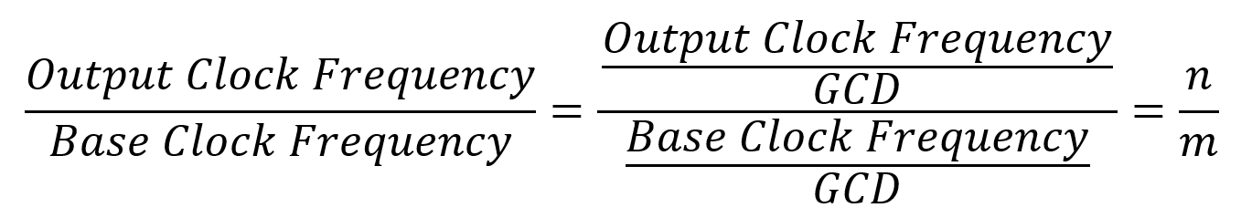
And mathematically, we need to do the following: 1. Find the GCD of the base clock and the output clock 2. Use the GCD to simplify the ratio between output clock and the base clock, i.e:
3. Once we get the simplified ratio of n over m, we can set the NCO counter like the following: a) Set the counter value to be zero (The initial phase) b) For every base clock cycle, counter = (counter + n) mod m c) Generate a pulse (output clock) every time the counter rolls over m
The code structure of the SpinalHDL module
Now let’s take a look at the code structure of the HelloWorld Example:
1. package
To
following the naming convention of JAVA package, the package name is
often the reverse form of a URL. But you are also free to choose other
name formats as you see fit. For example, in our FpgaLimerick repo, all
the common code is placed in a package called “common”
2. import
This is like the include section for Verilog or C++. And you can use scalafix to find and remove the unused imports.
3. case class extends Component
This
is similar to the “module” in Verilog. The SpinalHDL coding convention
recommends using “case class” instead of “class” in scala.
4.
The parameters of the module. Here we use the convention for parameters
as all capital letter with G_ prefix. (G stands for generics, a
reminiscent from VHDL)
5. A bundle for port list
6. The main body of the design (combinatorial logic and sequential logic)
7.
And a companion object that contains the main function, which will
generate the verilog / system verilog / VHDL based on the configuration.
Now,
comparing to verilog, it is a cinch for SpinalHDL to get GCD value, as
SpinalHDL is based on a high level programming language scala. If we
want to do the same implementation in verilog, we have to jump through a
lot of hoops to get the GCD value, as verilog’s system functions are
very primitive and do not cover GCD directly. Even if you can find a way
to calculate the GCD with verilog’s system functions, I bet the code
would be bulky and messy.
Configuration and Code Generation
The
Hello World uses the MainConfig to generate the code. The MainConfig
can be found in common/MainConfig.scala, which is derived from
SpinalConfig (in Spinal.scala from spinalhdl-core)
And in the MainConfig, the targetDirectory to be “gen”, and it sets the async reset to be active low.
Summary
From the Hello World example, it shows that the SpinalHDL is much more powerful and flexible for design parameterization.
Posted by
FPGA Limerick
at
March 11, 2023
|
0 Comments